Check my ciphering...

J!m

Veteran and General Yakker
Joined
Dec 24, 2019
Messages
9,382
Location
Connecticut
Tagline
BOT
#1
This fancy new table, on it's way from Japan to me, runs at 100VAC of course.

Here in 'murica we use 120VAC.

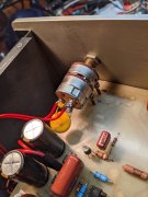
Transformer secondary output is 12VAC (0.6Amp) See attached schematic.

At 120VAC input, secondary output will be 14.4VAC

To drop that to 12VAC, I need a resistor (or two?). My calculations come up with 4 ohm, 2 watt rated.

My question is, since we are dealing with AC, should I have two resistors, one for each secondary leg coming off the transformer, or will one leg resistor do it?
Further- if I should add the resistor to both legs, should they both be 4 ohms, or should I use 2 ohms per leg (I doubt this, but this is where I need help)

And maybe I got it all screwed up.

Check please!

Thanks in advance!
 

Attachments

George S.

Veteran and General Yakker
Joined
Feb 18, 2020
Messages
4,588
#3
When I dropped the voltage on my PL2000 preamps, I added two resistors like so. The two red wires between electrolytics run from the transformer carrying approximately 19 VAC that needed to be reduced to below 18 VAC to keep from blowing the opamps. A resistor was added to the end of each wire, a piece of heat shrink added, then the free end of the resistor was soldered to the board. With AC, use two resistors. Even a half watt resistor is plenty strong to be mounted vertical by one lead. Just make sure it's tight against the board before you solder so the trace isn't stressed.
 

Attachments

J!m

Veteran and General Yakker
Joined
Dec 24, 2019
Messages
9,382
Location
Connecticut
Tagline
BOT
#4
So, two resistors is cool. I’m thinking of incorporating them with a switch, so you can run 100 or 120 volts.

But did you halve the calculated value (divide it between the two), or use the full calculated value on each leg?

So, in my case, I need 4 ohms to drop it. Should I put a 4 ohm on each secondary leg, or a 2 ohm on each leg? That’s where I’m not sure.
 

George S.

Veteran and General Yakker
Joined
Feb 18, 2020
Messages
4,588
#5
Split it between the two legs. But have extra values available to test for desired results. You may be surprised that 4 ohms total is not enough resistance even after working the equation. R=V/I. I is current in amps, until you measure it it's just a guess.
So 4=20/I. I assume you think it'll draw 5 amps?
 

J!m

Veteran and General Yakker
Joined
Dec 24, 2019
Messages
9,382
Location
Connecticut
Tagline
BOT
#6
According to the schematic it draws 0.6 amps.

2 watt resistors are suggested. (It’s less but 2 is common and better safe than sorry).
 

J!m

Veteran and General Yakker
Joined
Dec 24, 2019
Messages
9,382
Location
Connecticut
Tagline
BOT
#7
R=20/0.6

R=33.33

I think that’s right to drop the primary voltage.

But, I’m dropping (expected) secondary voltage from 14.4 to 12…

R=2.4/0.6

R=4

So your saying a 2 ohm on each output leg of the transformer will give me my 12 volts? (I think so but I want to be sure!)

I can order a pair of 2s and a pair of 4s easily enough I suppose…
 

George S.

Veteran and General Yakker
Joined
Feb 18, 2020
Messages
4,588
#9
If it was me, I'd have a wide assortment of low ohm value resistors. Calculate the value, then test and fine tune the value. Resistor assortments kits are cheap and come in handy.
 

George S.

Veteran and General Yakker
Joined
Feb 18, 2020
Messages
4,588
#12
Yup, maybe. But schematic shows 2 in, 2 out.
Wait until you get it, measure transformer size and mount, order a 120 to 12. Should be easy to find one that bolts right in and looks stock.
 

J!m

Veteran and General Yakker
Joined
Dec 24, 2019
Messages
9,382
Location
Connecticut
Tagline
BOT
#13
Finding a transformer is easy; finding a similar one (performance wise) is not. I've already been looking at Mouser...

They used an R-core specifically due to it's reduced EMI. Even better than a Toroid.

If it comes to it, I'll mount a toroid in an external box. That's be the only way to match the original (unless I have one wound).

Plus the resistors and a switch allows instant switching between 120 and 100, which is kinda nice.
 

nakdoc

Chief Journeyman
Joined
May 11, 2011
Messages
619
Location
Nashville, TN Music City
Tagline
highly biased
#15
Since the schematic shows a regulated power supply, I'd forget the resistors, and change C10 from 470 @16v to 470 @25v, change C14 to 220uf @ 25v, add a 10 ohm resistor in series with R10, and add a 16v 1 watt zener in parallel with C14. The change will give you a real regulated supply rather than the decoupled supply in the original design.
 

J!m

Veteran and General Yakker
Joined
Dec 24, 2019
Messages
9,382
Location
Connecticut
Tagline
BOT
#16
Sounds complicated…

I was kinda liking the idea of changing voltage with a switch too.

But that sounds like the right way to do it. Although, at that point, an external power supply probably makes sense.
 
Top