
Capstan shaft thrust movement
- Thread starter calman46
- Start date
Well, in general it should be so little you can’t feel it. Like a few tenths (0.0001”)
The Sony D5 suffers from a disintegrated felt washer that allows capstan movement. This skews the tape across the head. I source oil impregnated plastic replacement washers to replace the unavailable and prone to failure felt. (You still have to set the end float per the manual when done).
The Sony D5 suffers from a disintegrated felt washer that allows capstan movement. This skews the tape across the head. I source oil impregnated plastic replacement washers to replace the unavailable and prone to failure felt. (You still have to set the end float per the manual when done).
Ten thousandths?!? That’s high. But obviously go with what the manual says.
Since it’s Teac, run it by Sam and see if he has newer information.
Since it’s Teac, run it by Sam and see if he has newer information.
on the other side, 0.0001" would be 2 to 3 microns which is like saying no back-forth movement at all.
Interesting specs here. I am a Master Tool and Diemaker, and taught college level Metrology for over 20years. In my intro classes I did demonstrations where I would calibrate electronic gages capable of accuracy to 50 millionths of an inch. The temperature in a Metrology lab is always strictly maintained at (20 degrees C) 68 degrees F. In a simple demo, I would go over the calibration of the gage, and use gage blocks to measure and record the size at laboratory temperature. After noting the sizes of random gage blocks, I would hand them to several students to hold in their hands tightly. I also left some of the gage blocks on the granite plate, in ambient air where they were measured initially. Then after demoing calibration and applications, I would check the untouched gage blocks. These remained at the values initially measured.
I then asked students to set the gage blocks they had been holding in their hands, and remeasured those. Many of those blocks had grown +.002” just influenced by body temperature.
In the trade, we often had to fit punch and die, or mold halves within +/- .0002. This is always done at 68 degrees F, the idea being, if they match at 68 degrees, they both will grow at the same rate, being the same type of tool steel. Beryllium cores, fit to steel was another matter, or other materials used for slides, and cores. The operating temperature of a tool (mold / die) was of paramount importance to maintaining the fit of the components. Materials such as nylon would flash at more than .0005” (half a thousandth), so initial fit was critical. Materials such as 380 aluminum were forgiving up to a .003” initial fit. Those tools ran as hot as 580 degrees F, in critical areas in service. Water or oil cooling was employed to reduce molding/ casting surfaces to 70 to 100 degrees F. Many of the tools we built used electronic components to regulate tip temperatures (i.e. hot tip runner systems) and we always had to do the math to calculate tip growth relative to core growth and subsequent shut off clearances.
My point here is, when looking at mechanical fits with no thrust adjustment, the areal expansion (∆A/A0) depends on the material, including any gasketing, spacers etc. (but this says no thrust adjustment) and it’s coefficient of thermal expansion, and the normal operation temperature of the machine.
When looking at flywheel and capstan end clearances, operating temperature has to be considered.
As with any fit the molecular size of the lubrication used (i.e. weight of the oil, or dry lubricant also plays into it). In this case, no lubricant is used so the fit remains strictly an areal fit.
My two cents.
I do that boring and honing engines. I build all of my own torque plates for a mechanical “set” correctly torquing the fasteners top and bottom of the bore whether I am building an automotive, or motorcycle engine. I use a Sunnen CK-10 wet hone for cylinder finish. I hone at ambient temperature in the shop, but many builders heat their honing oil, and simulate the operating temp of the engine for final hone.
I drag raced my own car for many years, and tore the motor down when I reached 2% leak down. In a 10,000-rpm engine, cylinder size, fit, finish and roundness are super critical. Of course this plays into all of the engine fits, bearings, lifter bore clearance, valve to guide clearances etc. Temperature of the components, and their Metallurgical properties all are critical.
I drag raced my own car for many years, and tore the motor down when I reached 2% leak down. In a 10,000-rpm engine, cylinder size, fit, finish and roundness are super critical. Of course this plays into all of the engine fits, bearings, lifter bore clearance, valve to guide clearances etc. Temperature of the components, and their Metallurgical properties all are critical.

The Sony service manual states 0.05-0.2mm acceptable range (.0019-.0078") Almost six thousandths of tolerance. Not as tight as my memory remembered (but still difficult to measure repeatably). "There should be no play." in Sony's words.
If you can pull the capstan up and down (and feel it moving), it is moving too much. I don't see how guiding the tape at an angle leaving the head is a good thing...
If you can pull the capstan up and down (and feel it moving), it is moving too much. I don't see how guiding the tape at an angle leaving the head is a good thing...
I do that boring and honing engines. I build all of my own torque plates for a mechanical “set” correctly torquing the fasteners top and bottom of the bore whether I am building an automotive, or motorcycle engine. I use a Sunnen CK-10 wet hone for cylinder finish. I hone at ambient temperature in the shop, but many builders heat their honing oil, and simulate the operating temp of the engine for final hone.
I drag raced my own car for many years, and tore the motor down when I reached 2% leak down. In a 10,000-rpm engine, cylinder size, fit, finish and roundness are super critical. Of course this plays into all of the engine fits, bearings, lifter bore clearance, valve to guide clearances etc. Temperature of the components, and their Metallurgical properties all are critical.
View attachment 72414 View attachment 72415 View attachment 72416
IIRC, when Alex mentioned about the (about) 0.2mm , it was just in regards of a Sony deck.
anyway, I have a couple AIWA AD-F880 here... one is still factory tuned in this regard and i can clearly feel some noticeable back-forth play of the capstan shaft, maybe even more than 0.2mm, and the deck works fine with W&F in specs.
My other AD-F880 was clearly touched by someone and it had a lot of back-forth play... then, not being the factory setting anymore, I happened to experiment a bit in tuning the screws at the back of the capstan plate which are there to just set the back-forth play... and was tuning the screws while playing a speed tape with the WFGUI software running, to just see how the setting did influence the speed and W&F.
If i happened to tighten the screw in order to leave no play, speed dropped and W&F raised... and while loosening the screw to give some play the speed raised and the W&F dropped... while giving even more play (too much play, of course) the speed stayed there while the overall stability got worse... so, some play is needed... no play at all or too much play is not good.
But looking at the relatively macroscopic play on my "untouched" and well working AD-F880 here, I'd assume different mechs might want different ranges of thrust play.
Also, while experimenting of the AIWA, I've noticed that even if there was a lot of thrust play, as soon as I did push the "play" button (sorry for the repeat) , the rotating shaft/flywheel did accomodate to one position and didn't wander back and forth as I was expecting.
Last edited:
It may depend on the head configuration and tape guide system in use too. (in general: the transport)
With the D5 anyway, you have the thing slung over your shoulder while you dodge bullets in the field- having the tape move at a slight angle across the head, it will record the tracks at a slight angle. Play back on a stationary deck, and the tracks vary from "in" to "out" of alignment. Will this be audible? Dunno. Depends on the material I suspect. It will certainly be measurable I think it's safe to say.
And some end float is needed to prevent binding (the slowing you saw). And the way the bearings/bushings/thrust surfaces are configured dictates when the float is "good" and when it is "bad". The Sony uses two other washers, in addition to the (dissolved) felt one- one plastic and one bronze. The felt was oil impregnated for lubrication, but it evaporates and the dry felt turns to dust. You can grab the capstan and lift it up and down when the deck is on its back on a table top.
But overall, I would expect a bit more tolerance being allowed on a home deck, only because it is not being flung around during the recording process.
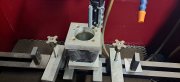
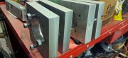
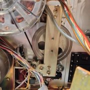
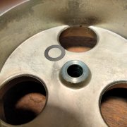
With the flywheel installed it would be hard to measure for the 0.01". The only adjustment is to move the flywheel on shaft (there is a notched spot in it). There is no back thrust adjustment just a pad. The other picture is of the flywheel and washer. There is burr around the edges of the flywheel where washer sits. This seems to be worn. I'm thinking of a drop of light oil here. The washer does sit flat. The capstan bushing face has light washer mark on it.
So the less back and forth play in capstan the better. My question is does the motor need a "little" play in the capstan when starting ?
So the less back and forth play in capstan the better. My question is does the motor need a "little" play in the capstan when starting ?
Attachments
-
 2.6 MB Views: 4
 -
 1.1 MB Views: 4
There should be *some* end float to avoid any binding... how much is up to the engineers.
I would say that if you have raised a burr and can see wear patterns, yes, you need oil and most likely you need a thicker washer.
You would set up a dial indicator with 0.0001 resolution and zero fully in one direction, and measure fully extended in the other direction.
If you have feeler gages, you might be able to do something with them, assuming there is access...
Hi Vince,
I don't know, what Alex was reffering to...but, 0,1 and 0,2-0,3 mm correspond to Studer A721 (Revox B215/H1) cassette deck...amongst others, likely. And, if I reccolect correctly, his align tapes are made on a modified Revox B215.
0,1 mm should be the longitudioanal/axial "play" of the capstan-shaft....OK, this I understand.
0,2-0,3 mm is/should be the "play" of the capstan-motor...Absolutely no idea/comprehension, what is ment!
Pinchroller "play"...0,1 mm
Pinchrollerarm "play"...0,1 mm.
A Studer A827/820 pinchroller "play"...0,4-1 mm....no mention of capstan shaft axial-play.
Just to throw some numbers around...Revox capstan shaft run-out 0,001 mm...Studer, half of that (half a micron).
So, 0,1 mm seems reasonable.
Last edited:
I was able to remove the burr no problem. That washer mics at 0.008" thick. I think setting the flywheel using the notch on capstan shaft is all I can do. You can adjust it some for more or less play but its minimal. I agree there should be some play to prevent binding. Teac assembly must have a had a quick way of doing it. The recap is done, back together it goes.