Baker/ Hughes Switching Power Supply

laatsch55

Administrator,
Staff member
Joined
Jan 14, 2011
Messages
74,240
Location
Gillette, Wyo.
Tagline
Halfbiass...Electron Herder and Backass Woof
#1
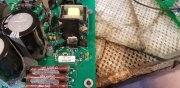
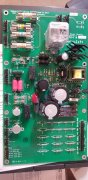
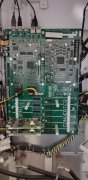
This power supply provides 28 volts DC to the main board, IGBT's, SCR's, converter and inverters. It also acts as a pass through fused source for the 1/2 HP heatsink cooling fan, and a resistor field for the DC bus voltage. It also provides 120 for the other ass't cooling fans scattered throughout the drive.
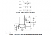
There is an LM 2577T-ADJ switching regulator, an IRBF 30 N-channel mosfet and a couple TO-220 cased diodes.
Incoming 120 is tapped to go through a bridge rectifier supplying +/- 162 vdc to the dc section.
My questions are;
Does the power supply need to be loaded to get relevant measurements?
And, why are they starting with +/- 163 dc?
 

Attachments

20tajk7

Chief Journeyman
Joined
Jul 26, 2011
Messages
747
Location
Absurdy, new name of France
Tagline
You never have too much tapedecks ^^
#2
Hi Lee, most switching power supplies should be loaded to be tested.
How does the 28Vdc is regulated ? Is it insulated to the 120Vac ? I didn't see any optocouplers.
The thermal switches S1 & S2 have an unusual location, usually these are on an heatsink, or maybe I miss something.
 

BlueCrab

Journeyman
Joined
Nov 10, 2019
Messages
229
#3
160vdc is the max you can get from 120vac (120 x 1.414 minus some drop across the diodes) without using a transformer or voltage doubler. With regards to whether or not it needs to see a load for relevant measurements, I would think not, but a light load of say 5k would allow the power supply to bleed off that 28vdc quickly.
 

laatsch55

Administrator,
Staff member
Joined
Jan 14, 2011
Messages
74,240
Location
Gillette, Wyo.
Tagline
Halfbiass...Electron Herder and Backass Woof
#4
Hi Lee, most switching power supplies should be loaded to be tested.
How does the 28Vdc is regulated ? Is it insulated to the 120Vac ? I didn't see any optocouplers.
The thermal switches S1 & S2 have an unusual location, usually these are on an heatsink, or maybe I miss something.

I think the 28 vdc is regulated by the LM 2577T-ADJ regulator.
 

laatsch55

Administrator,
Staff member
Joined
Jan 14, 2011
Messages
74,240
Location
Gillette, Wyo.
Tagline
Halfbiass...Electron Herder and Backass Woof
#5
160vdc is the max you can get from 120vac (120 x 1.414 minus some drop across the diodes) without using a transformer or voltage doubler. With regards to whether or not it needs to see a load for relevant measurements, I would think not, but a light load of say 5k would allow the power supply to bleed off that 28vdc quickly.
Thank you. I have some 24 volt fans that may load it enough..
 

laatsch55

Administrator,
Staff member
Joined
Jan 14, 2011
Messages
74,240
Location
Gillette, Wyo.
Tagline
Halfbiass...Electron Herder and Backass Woof
#6
Hi Lee, most switching power supplies should be loaded to be tested.
How does the 28Vdc is regulated ? Is it insulated to the 120Vac ? I didn't see any optocouplers.
The thermal switches S1 & S2 have an unusual location, usually these are on an heatsink, or maybe I miss something.
S1, S2 control the fans directed at the power supply board...
 

Gepetto

Administrator
Staff member
Joined
May 15, 2011
Messages
13,553
Location
Sterling, MA
Tagline
Old 'Arn Enthusiast
#10
I think the 28 vdc is regulated by the LM 2577T-ADJ regulator.
Indirectly perhaps Lee. I suspect that they are using the LM2577 as the controller for a forward converter based off of the switching transformer located just to the right of the LM2577. Does not look like a complex switching PSU.
 

Gepetto

Administrator
Staff member
Joined
May 15, 2011
Messages
13,553
Location
Sterling, MA
Tagline
Old 'Arn Enthusiast
#12
I should be seeing AC on the transformer windings then?
Yes, high frequency switching waveforms. I suspect you have this setup just by looking at the parts arrangement on that board. You should see a switching signal on pin 4 as well, that drives the forward converter. You will have your 162VDC from the bridge feeding the Vin end of the primary winding in this diagram. The other end of the primary will have the switchmode waveform on it.

1663295054877.png
 

Gepetto

Administrator
Staff member
Joined
May 15, 2011
Messages
13,553
Location
Sterling, MA
Tagline
Old 'Arn Enthusiast
#16
Pin 4 is likely driving your external IR MOSFET since the rated voltage on pin 4 is only up to 65V so they probably have some configuration that has pin 4 of the LM2577 drive that MOSFET gate.

If you get stumped, you can send over one and I will help you fix it Lee. I don't charge $4768...
 

laatsch55

Administrator,
Staff member
Joined
Jan 14, 2011
Messages
74,240
Location
Gillette, Wyo.
Tagline
Halfbiass...Electron Herder and Backass Woof
#17
Ok...I am getting no Vin on the 2577..it appears to be fed by the N-channel Mosfet to the right of it. Taking measurements from a known good power supply I have 168 vdc going to the Drain lead and 15.23 vdc on the source lead and 14.82vdc on the gate lead.
On the non-functioning supply I have 168 vac to the drain, 0 volts on the gate, 0 volts on the source...
I'm guessing the mosfet is bad..
 

Attachments

Joined
Apr 1, 2015
Messages
133
Tagline
---
#18
You may want to do yourself a favor and get some horsepower into your corner, get a Atlas Peak transistor tester. A 55 will cut it, the 75 interfaces to usb.
 

Gepetto

Administrator
Staff member
Joined
May 15, 2011
Messages
13,553
Location
Sterling, MA
Tagline
Old 'Arn Enthusiast
#19
Ok...I am getting no Vin on the 2577..it appears to be fed by the N-channel Mosfet to the right of it. Taking measurements from a known good power supply I have 168 vdc going to the Drain lead and 15.23 vdc on the source lead and 14.82vdc on the gate lead.
On the non-functioning supply I have 168 vac to the drain, 0 volts on the gate, 0 volts on the source...
I'm guessing the mosfet is bad..
Not sure I would reach that conclusion Lee...gate at zero means nothing is driving it. The source will likely be tied to ground so that will be zero. With no gate drive, the drain will be at the B+ potential of the transformer winding it is driving (168V).
 

laatsch55

Administrator,
Staff member
Joined
Jan 14, 2011
Messages
74,240
Location
Gillette, Wyo.
Tagline
Halfbiass...Electron Herder and Backass Woof
#20
Pin 4 is likely driving your external IR MOSFET since the rated voltage on pin 4 is only up to 65V so they probably have some configuration that has pin 4 of the LM2577 drive that MOSFET gate.

If you get stumped, you can send over one and I will help you fix it Lee. I don't charge $4768...

That may be where we wind up Joe.

I'll refgerence ground on pin 3 of the LM and check pin 4...pin 4 is going to the source pin of the mosfet..
 
Top