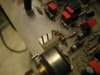
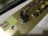
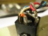
Found: stub of orange wire snipped from headphone jack terminal #4
Thanks Lee, thanks Nav for providing that material,
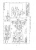
Had a read through the troubleshooting section with regards to "no headphone output" and the suggestion is to check Pin 6 of Z104. It also says to use an AC voltmeter and an oscilloscope. I have a DMM but no scope. Nothing was mentioned about a signal source but unless a recorded 30 Hz test tone on a CD will do, I can probably borrow a frequency generator again and perhaps even a scope although I've never used one before. If there is undistorted output at Z104 pin 6, I am to check and/or replace Q101/201 & Q201/Q202.
One thing I saw on close examination of the headphone jack itself was the stub of an orange insulated wire soldered to lug #4. My schematic reading skills are not great and I have not been able to locate where this wire may go. Any educated guesses as to what it attaches to? Long shot hope is that this missing wire is is why the headphone jack is dead.
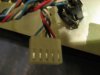
FWIW, I checked the switched amplifier output jacks and inserting a headphone plug interrupts the output signal as it is supposed to, just no signal going to the headphones.