
No more 60 Hz hum in a PL2000 preamp.
- Thread starter George S.
- Start date
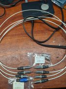
The cables are done. Belden 83284 RG-316, Switchcraft 093-148 RCAs, Switchcraft 093-156 3.5 mm stereo plug. Short pieces of automotive vacuum hose to bush the cable entering the jacks. Will try to do some testing tomorrow. Testing is done 1 channel at a time so I made a 3.5 mm jack cable wired for each channel. The sound card is RCA out and 3.5 stereo in. Blue tape on right channel until I pick up some right diameter red shrink or tape.
Last edited:
Have you snubbed the bridge rectifier and considered inserting ~10 ohms into each AC secondary leg where it connects to the bridge?
You have every harmonic of 60Hz represented in your spectrum analysis. 60, 120, 180, 240, 300, 360, 420, 480, 560, 600, 660 is quite muted, 720 and so on...
You have every harmonic of 60Hz represented in your spectrum analysis. 60, 120, 180, 240, 300, 360, 420, 480, 560, 600, 660 is quite muted, 720 and so on...
Would inserting 10ohms on the ac lines to the bridge on a 400 / 700 reduce 60hz noise any appreciable amount without cutting output power ?
I've been reading about snubbers for several days now. From what I understand (which is little!) the .01 uF films I added parallel to the rectifiers shifted the ringing resonance to a lower frequency. The ringing is still there, just at a lower frequency. The resistor is the most critical part as it has to match the characteristic impedance of the circuit.
So, rather than add parallel caps, I'm reading that the best way to tame this is to look at the ringing with a scope, and add a appropriate r-c between the secondaries. I have a good analog scope, so I'm going to try and learn how to do this.
The new test leads made little difference,(but were well worth making!) and I'm fairly sure the REW results are fairly accurate.
At this point I've removed the caps, untwisted the primaries and secondaries and zip tied them together as original.
Now going to learn how to scope that 60 Hz on the secondaries. Thing I'm most concerned about is the grounding of the preamp and scope.
Making progress. Luckily I have all the documentation and spent several weeks last winter rebuilding and aligning it. Have never used a probe before. Have run the preamp output into it to look at the stereo wave forms. Power supply had burnt molex connectors. Was easy fix as I also have a parts unit.
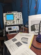
Hmm, well, I think I'm doing this correct. Probe is set to X1, attached to one of the two secondaries between the transformer and board. Checking voltage with the Fluke I get 8.6 VAC between each of the two secondaries and center tap. Very, very, ugly. The HP displays a perfect sine wave from the signal generator, so I believe these results are accurate.
Going to build a "Quasimodo the bell ringer" test jig to solve the issue. Some interesting reading here if your interested. Will try it on all my PL gear if successful. https://www.diyaudio.com/forums/pow...sformer-snubber-using-quasimodo-test-jig.html
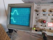
Here are some pictures with my probe grounded (way too noisy when not grounded):
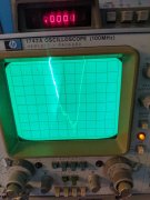
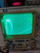
Outputs of the Transformer Secondary Windings (38V Peak) Don't know why the sine waves are clipped, this is "in circuit" measuring.
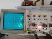
Outputs of the Bridge Rectifier (DC with .4V Peak AC Sawtooth) .01uF snubber caps across the bridge rectifier diodes will likely fix this.
Outputs of the Transformer Secondary Windings (38V Peak) Don't know why the sine waves are clipped, this is "in circuit" measuring.
Outputs of the Bridge Rectifier (DC with .4V Peak AC Sawtooth) .01uF snubber caps across the bridge rectifier diodes will likely fix this.
Mark, I appreciate the photos. I'm on the road working all week so I'll have to use my free time watching videos on oscilloscope operation and learn more. In the first photo are you sure that's 38 V? Would be if probe is set at 10X. This is a PL2000? Sure that's not 3.8 V or slightly higher without the clipping with a transformer wired for 240 running on 120?
From what I read about snubbers, the resistor is the critical component that damps the ringing of the diodes switching on and off. Just adding parallel caps like a .01 uF simply shifts the ringing frequency lower, but it's still there.
I'm going to pursue learning how to add the correct resistor and capacitor between the primaries rather than adding caps parallel with the diodes. From what I've read, I think this is the way to go, but my knowledge is limited, maybe I am misunderstanding the source of the 60 Hz I'm chasing. Maybe it's a ghost like my elderly father who was a electronics tech all his life says it is. I don't know. Thanks.
Sorry, you caught my omission, I am using two 10X probes. The pictures I posted are the 'before' pictures, I hope to take the same pictures after I add the .01uF snubber caps and the RC snubber circuit. Also, the series 10 Ohm 2W resistors to each secondary leg.
I think the clipping, if it is clipping, is coming from something downstream. I have never seen clipping like that coming from a power supply with no load. It may be the TIS97 transistor that is being used as a Zener diode to limit the voltage, not sure.
I was reading 15.38VAC on one secondary leg to the CT (Ground) and 15.40VAC on the other secondary leg to CT. Leg to leg measured 30.80VAC on the HP RMS Voltmeter. These are nominal voltages according to the Service Manual, which describes the power supply as +/-17VDC.
My understanding is that the .01 caps across the diodes suppress (snub) the voltage spike as the diodes switch on and off (as the cap charges and discharges), this is a common and effective practice. The series resistors in the legs of the secondary leads provide a discharge path for the bridge rectifier snubber .01uF capacitors. The other half of this noise filtering exercise is the 60Hz RC filter across the transformer secondary winding. Here:
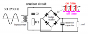
According to the article, you can mathematically determine optimum values for the film capacitor, C1; and the discharge resistor, R1; between 47nF-1uF and 4.7-47 Ohms. However, the nominal values of 220nF/50V and 10 Ohms/1W should work fine. I will try those values and report back.
I think the clipping, if it is clipping, is coming from something downstream. I have never seen clipping like that coming from a power supply with no load. It may be the TIS97 transistor that is being used as a Zener diode to limit the voltage, not sure.
I was reading 15.38VAC on one secondary leg to the CT (Ground) and 15.40VAC on the other secondary leg to CT. Leg to leg measured 30.80VAC on the HP RMS Voltmeter. These are nominal voltages according to the Service Manual, which describes the power supply as +/-17VDC.
My understanding is that the .01 caps across the diodes suppress (snub) the voltage spike as the diodes switch on and off (as the cap charges and discharges), this is a common and effective practice. The series resistors in the legs of the secondary leads provide a discharge path for the bridge rectifier snubber .01uF capacitors. The other half of this noise filtering exercise is the 60Hz RC filter across the transformer secondary winding. Here:
According to the article, you can mathematically determine optimum values for the film capacitor, C1; and the discharge resistor, R1; between 47nF-1uF and 4.7-47 Ohms. However, the nominal values of 220nF/50V and 10 Ohms/1W should work fine. I will try those values and report back.
https://forums.phxaudiotape.com/threads/pl2000-led-driver.9581/. For the LED driver fix. Spent some time last winter looking for a modern current production sub for Q1 but got sidetracked and never got back to it.
- Joined
- Jan 14, 2011
- Messages
- 74,214
- Location
- Gillette, Wyo.
- Tagline
- Halfbiass...Electron Herder and Backass Woof
Looks like NTE199 is equivalent to TIS97. I have a bunch of those TIS97s in old Cylon meter boards. The TIS97s are used in Mini-Moogs in some type of ladder arrangement and appears those guys want NOS examples and match them for gain. Going to continue looking for a sub. The GES97 appears to predate the internet, sparse info. Both of my PL2000s came with one of each, but with reversed locations. Figures!