
Nice 400-ll to rebuild
- Thread starter grapplesaw
- Start date
So Steve Mantz is still around? I spoke to him about 10 years ago. I have a schematic, from 2009, of a mod he did to eliminate the boot strap circuit by adding a transistor between the collector of the bias transistor and V+. He kept the discreet front end circuit. He also added what he called base stopper resistors on the predrivers. I'm reluctant to share it here as he may consider it proprietary.
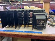
When I test an amp after rebuild/repair I run it at about 1/3 of it's rated output which is worst case for temperature rise. I get the case temps of the ouptuts to about 85C (185F) as read with an infrared gun. Consisterntly, the second transistor down from the top is 8-10 degrees C above the top transistor in the column. It's no mystery if you look at the spacing on the heatsinks. The bottom transistor (the driver) is also hotter than the one above it for the same reason.
I'm assuming the goal of the mod is to disperse the heat dissipation of the outputs across 4 transistors rather than 3. The procedure I noted may help confirm the goal is met. It may also indicate the added driver is getting quite hot. The lowest output (used to be the driver) may be the hottest of all.
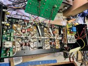
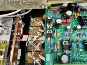
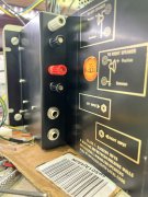
On a different note, I noticed in one of the photos it appears that the bias transistor is an isolated case TO220. I've used MJF31's in that application before and much prefer it over the 2N3403/P-strap. The TO220 pin spacing is 0.1" which is also the same spacing for three wire computer fan connectors. Cut the cables off of a couple cheap fan motors and push the connector on the transistor leads. It's a very snug fit and requires no soldering on the transistor leads.
When I test an amp after rebuild/repair I run it at about 1/3 of it's rated output which is worst case for temperature rise. I get the case temps of the ouptuts to about 85C (185F) as read with an infrared gun. Consisterntly, the second transistor down from the top is 8-10 degrees C above the top transistor in the column. It's no mystery if you look at the spacing on the heatsinks. The bottom transistor (the driver) is also hotter than the one above it for the same reason.
I'm assuming the goal of the mod is to disperse the heat dissipation of the outputs across 4 transistors rather than 3. The procedure I noted may help confirm the goal is met. It may also indicate the added driver is getting quite hot. The lowest output (used to be the driver) may be the hottest of all.
On a different note, I noticed in one of the photos it appears that the bias transistor is an isolated case TO220. I've used MJF31's in that application before and much prefer it over the 2N3403/P-strap. The TO220 pin spacing is 0.1" which is also the same spacing for three wire computer fan connectors. Cut the cables off of a couple cheap fan motors and push the connector on the transistor leads. It's a very snug fit and requires no soldering on the transistor leads.
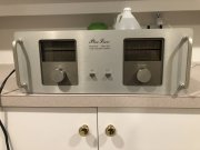
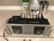
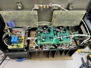
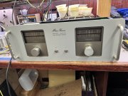
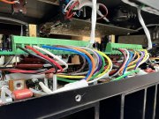
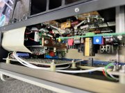
It’s alive!!
Just setting up.
small fuses for an hour the we boogie.
Bias .36v
Offset .22 mv right 1.19mv left
Voyage board 30.86/88
Rails with 118 v in 170.6 total( she a hottie)
noise is low
Plastic outputs are 10* hotter at idle
View attachment 59824 View attachment 59825 View attachment 59826 View attachment 59827 View attachment 59828 View attachment 59829 View attachment 59830
- Joined
- Jan 14, 2011
- Messages
- 74,244
- Location
- Gillette, Wyo.
- Tagline
- Halfbiass...Electron Herder and Backass Woof
It’s alive!!
Just setting up.
small fuses for an hour the we boogie.
Bias .36v
Offset .22 mv right 1.19mv left
Voyage board 30.86/88
Rails with 118 v in 170.6 total( she a hottie)
noise is low
Plastic outputs are 10* hotter at idle
View attachment 59824 View attachment 59825 View attachment 59826 View attachment 59827 View attachment 59828 View attachment 59829 View attachment 59830
Just setting up.
small fuses for an hour the we boogie.
Bias .36v
Offset .22 mv right 1.19mv left
Voyage board 30.86/88
Rails with 118 v in 170.6 total( she a hottie)
noise is low
Plastic outputs are 10* hotter at idle
View attachment 59824 View attachment 59825 View attachment 59826 View attachment 59827 View attachment 59828 View attachment 59829 View attachment 59830
- Joined
- May 1, 2013
- Messages
- 7,163
- Location
- Australia
- Tagline
- Those who enter the man cave will get WOPLed
- Joined
- Jan 14, 2011
- Messages
- 74,244
- Location
- Gillette, Wyo.
- Tagline
- Halfbiass...Electron Herder and Backass Woof
- Joined
- Jan 14, 2011
- Messages
- 74,244
- Location
- Gillette, Wyo.
- Tagline
- Halfbiass...Electron Herder and Backass Woof
Glen,
Can you elaborate on the double diode setup at D52 and D53 along with any other mods you did on the WOA Control Board?
Might be something I want to try...
Can you elaborate on the double diode setup at D52 and D53 along with any other mods you did on the WOA Control Board?
Might be something I want to try...
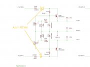
Good eagle eye there, how many more tweaks can you find?
so to the answer
I put a 1n5366bg Zenor diode to act as a max voltage regulator ahead of the rest of the regulator section. It’s a safety valve if you like. This limits down stream voltage to 39 voltes in both + and - feeds
First the 1n 4004 rectifier then the Zenor in reverse flow
For those interested here is a link to how Zenor diodes work
https://www.circuitbread.com/tutorials/what-is-a-zener-diode-and-how-does-it-work
I’ve attach the schematic modification which is done to both channels . Very easy to add just stand then upright and bend legs to meet then solder together. Please note the opposed orientation of the two pairs. Get it wrong and not much good.
this addition was suggested to me by Joe when I had a failure in a high voltage d500 input and I just carry on with it. It’s just a small amount of money after all
Thanks for the Question Mark
Good eagle eye there, how many more tweaks can you find?
so to the answer
I put a 1n5366bg Zenor diode to act as a max voltage regulator ahead of the rest of the regulator section. It’s a safety valve if you like. This limits down stream voltage to 39 voltes in both + and - feeds
First the 1n 4004 rectifier then the Zenor in reverse flow
For those interested here is a link to how Zenor diodes work
https://www.circuitbread.com/tutorials/what-is-a-zener-diode-and-how-does-it-work
I’ve attach the schematic modification which is done to both channels . Very easy to add just stand then upright and bend legs to meet then solder together. Please note the opposed orientation of the two pairs. Get it wrong and not much good.
this addition was suggested to me by Joe when I had a failure in a high voltage d500 input and I just carry on with it. It’s just a small amount of money after all View attachment 79702
 ...just glad it works and I'll take your word for why!!!
I put a 1n5366bg Zenor diode to act as a max voltage regulator ahead of the rest of the regulator section. It’s a safety valve if you like. This limits down stream voltage to 39 voltes in both + and - feeds
First the 1n 4004 rectifier then the Zenor in reverse flow
First the 1n 4004 rectifier then the Zenor in reverse flow
I did see other tweaks in the amplifier, but I wanted to concentrate on the WOA Control Board for now. Did I miss any other tweaks on the Control Board?
Thanks, Mark
Glen, nice work with that Zener diode addition. I don't see a downside (i.e. noisy diode switching or heat generation) and the rating of the 1N5366 diode is 5 Watts, which should be enough to give it long life. If Joe specified 39 Volts (an odd number) he must have had some engineering technical data in mind.
I did see other tweaks in the amplifier, but I wanted to concentrate on the WOA Control Board for now. Did I miss any other tweaks on the Control Board?
Thanks, Mark
I did see other tweaks in the amplifier, but I wanted to concentrate on the WOA Control Board for now. Did I miss any other tweaks on the Control Board?
Thanks, Mark
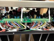
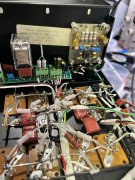
this unit has extra row of MjL21196/96 as first drivers to the now 8 outputs to each channel
I will stat testing to at 4 ohms and below. Looking for stable 2 ohm capabilities , not that I need it but I am looking for a set of infinity Kappa’s
Last edited: