Phase Linear 5000 Series 2

George S.

Veteran and General Yakker
Joined
Feb 18, 2020
Messages
4,589
#1
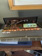
Opened it up this morning to check it out. This was a eBay purchase a while back, and it's sat in the closet until now. I plugged it in when I first got it, tuning was wonky, the LEDs for stereo and multipath didn't light in concert with the received signal, nor did the meters. Also had a little bit of play in the string tuning assembly.
The caps and bulbs look all original, and it's very clean inside. First thing I checked was the 19 MHz pilot frequency, was about 400 Hz too high. This seems to be a common issue as there's several posts about this on the internet. Some replace a ceramic cap that's said to have drifted over time causing this. The adjustment pot had enough range to where I could adjust it to 19 MHz spec.
So I plugged it in, per the photo, and now the LEDs and meters work perfectly in sync with the received signal strength,
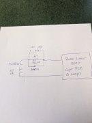
This is going to be a easy one to recap. Looks like 5 electrolytics and the 1 ceramic for the pilot frequency. The original festoon lamps are no longer available anywhere, but it looks like 6x42mm LED fuse lamps made for McIntosh applications may work. A SMD resistor may or may not need to be increased for the 5000s higher lamp voltage. Easy enough to do if needed.
As it is now, it's a good sounding tuner. Been sitting here listening to a Cleveland OH rock station. Will update.
 

Attachments

George S.

Veteran and General Yakker
Joined
Feb 18, 2020
Messages
4,589
#2
I have a little down time today, so I drew out a schematic and have a question about the PL5000 lamp circuit. This sketch is directly from the service manual. Question is: Why did they include the 1N4004 diode? I don't understand it's purpose.
 

Attachments

George S.

Veteran and General Yakker
Joined
Feb 18, 2020
Messages
4,589
#4
Has to be a snubber or flyback diode, that resistor is a highly inductive wire wound cement type. Those original festoon lamps are marked 12 volts, AC voltage at the lamps. The 6x42mm Fuse LED lamps I ordered are marked AC 6.3 volts. Should be very simple to rework this circuit to appx 6 VAC, and get rid of the cement resistor because the new lamps are LED. Just need to figure out the current draw of 13 LED lamp assemblies and calculate the value and wattage of the new resistor.
This would be much better than modding the lamps to work at 12 VAC.
 

Gepetto

Administrator
Staff member
Joined
May 15, 2011
Messages
13,553
Location
Sterling, MA
Tagline
Old 'Arn Enthusiast
#5
I have a little down time today, so I drew out a schematic and have a question about the PL5000 lamp circuit. This sketch is directly from the service manual. Question is: Why did they include the 1N4004 diode? I don't understand it's purpose.
You sure you transcribed it correctly George?
 

Gepetto

Administrator
Staff member
Joined
May 15, 2011
Messages
13,553
Location
Sterling, MA
Tagline
Old 'Arn Enthusiast
#7
No, not a fly back. For the forward half of the cycle, the voltage to the lamp chain only suffers a single diode drop from the transformer voltage. For the negative half of the cycle, the lamps see the full drop imposed by the 3 ohm resistor. It is an average current limiting scheme, hokey but that is what it is. If your eyes were fast enough you would see the lamp brightness increase during one half cycle and dim for the other half. The thermal inertia of the filament masks this coupled with your ocular threshold of 50msec filtering out such flicker. You may see this with LEDs however
 

laatsch55

Administrator,
Staff member
Joined
Jan 14, 2011
Messages
74,240
Location
Gillette, Wyo.
Tagline
Halfbiass...Electron Herder and Backass Woof
#11
No, not a fly back. For the forward half of the cycle, the voltage to the lamp chain only suffers a single diode drop from the transformer voltage. For the negative half of the cycle, the lamps see the full drop imposed by the 3 ohm resistor. It is an average current limiting scheme, hokey but that is what it is. If your eyes were fast enough you would see the lamp brightness increase during one half cycle and dim for the other half. The thermal inertia of the filament masks this coupled with your ocular threshold of 50msec filtering out such flicker. You may see this with LEDs however


"Ocular threshold"...damn Joe...what is that in Hz?
 

Gepetto

Administrator
Staff member
Joined
May 15, 2011
Messages
13,553
Location
Sterling, MA
Tagline
Old 'Arn Enthusiast
#12
"Ocular threshold"...damn Joe...what is that in Hz?
somewhere around 40 Hz Lee which is why they set refresh on video screens above 50Hz to eliminate that annoying flicker. I am sure it varies from person to person, like hearing and such.
 

George S.

Veteran and General Yakker
Joined
Feb 18, 2020
Messages
4,589
#15
My 5000 Series 1 is exactly the same.
I looked for a S2 service manual and no sign of one anywhere. I think the S1+2s are exactly the same other than the dial color and rack handles. I have found a S2 owners manual, shows the black dial.
 

George S.

Veteran and General Yakker
Joined
Feb 18, 2020
Messages
4,589
#20
Nope, the 5100 was. And all 5100s are S2. I have a 5100 totally rebuilt and recapped, pure Pioneer, AM+FM. We're talking 5000 S1+2 here. The big-uns with the big k nob. Old timey PL, FM only, 13 12 volt lamps for illuminating a white tuning dial on the S1, or black dial on the S2.
 
Top