No more 60 Hz hum in a PL2000 preamp.

Gepetto

Administrator
Staff member
Joined
May 15, 2011
Messages
13,536
Location
Sterling, MA
Tagline
Old 'Arn Enthusiast
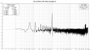
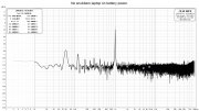
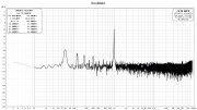
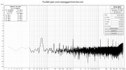
Got the Quasimodos built and 3 transformers tested. Unfortunately all 3 are dual primary export, however they all test very similar, so that's good. All were tested with the recommended TDK film capacitors .01 uF and.15 uF, and a 1k ohm variable resistor used to arrive at the correct value. Resistor value didn't seem to be highly critical, with a give and take of approximately 20 ohms from the optimum damping. 120 ohms seems to optimum, but good damping was also seen at 100 and 140 ohms. I used 100 ohm because that's what had on hand.


View attachment 54355 View attachment 54357 View attachment 54358 View attachment 54356
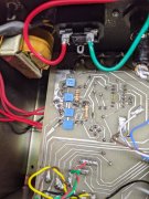
The PL2000 transformer has two secondary outputs and a center tap. A .01 uF gets soldered between each secondary and center tap, and a .15 uF and 120 ohm carbon film in series also gets soldered between each secondary and center tap.
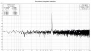
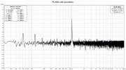
Can I hear any difference? No, not really. The preamp had no hum or noise before. The spectrum analyzer does show some improvement. After reading Mark Johnsons' paper (he designed the Quasimodo) published in https://linearaudio.net/sites/linearaudio.net/files/volumes/v10 mj abstract.png, I'm going to try some Vishay SBYV27-200 rectifier diodes.
View attachment 54359
The old PL2000 circuit board is starting to get really beat. That's OK, It'll remain a test unit.
Do you see an 83 KHz spike in your spectrum analysis?
 

George S.

Veteran and General Yakker
Joined
Feb 18, 2020
Messages
4,585
As you can see I still have some 60 hZ line noise and 120 hZ which I assume is rectifier noise. Tried removing the voltage dropping resistors from the two secondaries, using a center tap resistor to drop the voltage, but the B+ and B- became unbalanced. Had appx 4 volts difference. So went back to secondary mounted voltage dropping resistors.
With no voltage dropping resistors had 20 volts total nicely balanced with B+ and B- each at 10 volts. Added a 47 ohm to each leg to bring each down to 8 volts for a total of 16 volts.
Wish I didn't need those dropping resistors there, but I fail to see where I can mount them without cutting traces.
Been thinking about maybe perhaps soldering them in series with the rectifier diodes and dropping the DC rather than AC. Diode lead in one hole and resistor lead in the next.
I sure would appreciate your thoughts. Thanks!
souncard.jpg pl.jpg
 

Gepetto

Administrator
Staff member
Joined
May 15, 2011
Messages
13,536
Location
Sterling, MA
Tagline
Old 'Arn Enthusiast
As you can see I still have some 60 hZ line noise and 120 hZ which I assume is rectifier noise. Tried removing the voltage dropping resistors from the two secondaries, using a center tap resistor to drop the voltage, but the B+ and B- became unbalanced. Had appx 4 volts difference. So went back to secondary mounted voltage dropping resistors.
With no voltage dropping resistors had 20 volts total nicely balanced with B+ and B- each at 10 volts. Added a 47 ohm to each leg to bring each down to 8 volts for a total of 16 volts.
Wish I didn't need those dropping resistors there, but I fail to see where I can mount them without cutting traces.
Been thinking about maybe perhaps soldering them in series with the rectifier diodes and dropping the DC rather than AC. Diode lead in one hole and resistor lead in the next.
I sure would appreciate your thoughts. Thanks!
View attachment 54370 View attachment 54371
Dropping the DC does not have the damping effect on your resonance that putting them in series with the secondary leads does. It will drop the DC but won't help with your AC noise. Put the resistors in series with the transformer secondary leads and shrink wrap them. No board alteration needed.

I take it your spectrum analyzer does not go up to 100 Khz...just 20Khz
 

mlucitt

Veteran and General Yakker
Joined
Jun 24, 2011
Messages
3,367
Location
Jacksonville, FL
nicely balanced with B+ and B- each at 10 volts.
George, where did you measure your +10V and -10V? Was that with the power supply connected to the load (preamplifier)?
The voltage sensitive devices in the PL2000 are the upgraded 2134 OPAMPs, and the specifications of those devices are production tested with +/-15V supplies, a total of 30VDC across the OPAMPs. So, according to the OPA 2134 datasheet, your 47 Ohm voltage dropping resistors are not necessary because without them you have 20VDC across the OPAMPs. But as Joe stated, 10 Ohm resistors in the transformer AC secondary would be beneficial for damping some of the 60Hz resonance.

Thoughts?
 

George S.

Veteran and General Yakker
Joined
Feb 18, 2020
Messages
4,585
Dropping the DC does not have the damping effect on your resonance that putting them in series with the secondary leads does. It will drop the DC but won't help with your AC noise. Put the resistors in series with the transformer secondary leads and shrink wrap them. No board alteration needed.

I take it your spectrum analyzer does not go up to 100 Khz...just 20Khz
Well crap, read it as 83 hZ not khZ. Will set sound card resolution at 198 khZ and should measure out to half that value. It's going to be coming weekend before I can measure
 

George S.

Veteran and General Yakker
Joined
Feb 18, 2020
Messages
4,585
George, where did you measure your +10V and -10V? Was that with the power supply connected to the load (preamplifier)?
The voltage sensitive devices in the PL2000 are the upgraded 2134 OPAMPs, and the specifications of those devices are production tested with +/-15V supplies, a total of 30VDC across the OPAMPs. So, according to the OPA 2134 datasheet, your 47 Ohm voltage dropping resistors are not necessary because without them you have 20VDC across the OPAMPs. But as Joe stated, 10 Ohm resistors in the transformer AC secondary would be beneficial for damping some of the 60Hz resonance.

Thoughts?
Mark, if those OPA2134s are tested at 15 volts per rail, then that highly simplifies matters. I thought they were rated at 9 volts per rail.
Yes, was getting a solid 10 volts on each B+ and B- with no dropping resistors in circuit, and the original opamps in for load. Yeah, I know, the original opamps were rated 18 v max, was afraid of blowing those browndogs.
So, going to test with soft recovery diodes, no voltage dropping resistors, and the C C-R snubber. This time will measure out to appx 90 khZ and look for any spikes at 83 khZ or elsewhere.
 
Last edited:

Gepetto

Administrator
Staff member
Joined
May 15, 2011
Messages
13,536
Location
Sterling, MA
Tagline
Old 'Arn Enthusiast
Well crap, read it as 83 hZ not khZ. Will set sound card resolution at 198 khZ and should measure out to half that value. It's going to be coming weekend before I can measure
Your original transformer resonance fundamental was somewhere around 83Khz. You should measure unsnubbed and snubbed
 

George S.

Veteran and General Yakker
Joined
Feb 18, 2020
Messages
4,585
George, where did you measure your +10V and -10V? Was that with the power supply connected to the load (preamplifier)?
The voltage sensitive devices in the PL2000 are the upgraded 2134 OPAMPs, and the specifications of those devices are production tested with +/-15V supplies, a total of 30VDC across the OPAMPs. So, according to the OPA 2134 datasheet, your 47 Ohm voltage dropping resistors are not necessary because without them you have 20VDC across the OPAMPs. But as Joe stated, 10 Ohm resistors in the transformer AC secondary would be beneficial for damping some of the 60Hz resonance.

Thoughts?
Mark, my background in automotive wiring and ignorance of electronics has bit me again. From the OPA2134 data sheet "They can be operated from ±2.5-V to ±18-V power supplies.". I looked at that when I got the Browndogs and read it as 18 volts total, not per rail. Therefore the 10 volts per rail I'm getting with no dropping resistors is within spec. Thanks for catching my error!
Going to test without the 10 ohm in series first. Then will try that if no joy.
 

Gepetto

Administrator
Staff member
Joined
May 15, 2011
Messages
13,536
Location
Sterling, MA
Tagline
Old 'Arn Enthusiast
Mark, my background in automotive wiring and ignorance of electronics has bit me again. From the OPA2134 data sheet "They can be operated from ±2.5-V to ±18-V power supplies.". I looked at that when I got the Browndogs and read it as 18 volts total, not per rail. Therefore the 10 volts per rail I'm getting with no dropping resistors is within spec. Thanks for catching my error!
Going to test without the 10 ohm in series first. Then will try that if no joy.
Hi George
I recall from your earlier thread on this that the rail voltages were more like +/-20V. My PL2000 rails measure +/- 19.6V in the stock configuration. Well above the absolute maximum allowed on op amps. The series resistors you cite brought those rails down to ~+/- 15V after we had our earlier dialog. Beware!!
 

George S.

Veteran and General Yakker
Joined
Feb 18, 2020
Messages
4,585
Hi George
I recall from your earlier thread on this that the rail voltages were more like +/-20V. My PL2000 rails measure +/- 19.6V in the stock configuration. Well above the absolute maximum allowed on op amps. The series resistors you cite brought those rails down to ~+/- 15V after we had our earlier dialog. Beware!!
Maybe I misunderstand the way rail voltage is specified on the OPA2134 data sheet. "They can be operated from ±2.5-V to ±18-V power supplies.". Does +/-18 mean a +18 and -18 per rail for a total of 36, or does it mean + and - per rail for a total of 18?
I originally thought + and - rails couldn't exceed 18 volts total for the original opamps AND the Browndog OPA 2134s. This is THE reason for dropping the voltage and reason I have a 47 ohm in series with each secondary before the rectifiers.
Marks post #105 about +/- 15 and 30 volts across the opamp has me confused and questioning.
I'm thinking +/- secondary voltage should be balanced, should be around +8 and -8 to allow for any surge, +9 and -9 is the absolute maximum and no real good reason to be there.
 

Gepetto

Administrator
Staff member
Joined
May 15, 2011
Messages
13,536
Location
Sterling, MA
Tagline
Old 'Arn Enthusiast
Maybe I misunderstand the way rail voltage is specified on the OPA2134 data sheet. "They can be operated from ±2.5-V to ±18-V power supplies.". Does +/-18 mean a +18 and -18 per rail for a total of 36, or does it mean + and - per rail for a total of 18?
I originally thought + and - rails couldn't exceed 18 volts total for the original opamps AND the Browndog OPA 2134s. This is THE reason for dropping the voltage and reason I have a 47 ohm in series with each secondary before the rectifiers.
Marks post #105 about +/- 15 and 30 volts across the opamp has me confused and questioning.
I'm thinking +/- secondary voltage should be balanced, should be around +8 and -8 to allow for any surge, +9 and -9 is the absolute maximum and no real good reason to be there.
You should strive for 30V across the op amp. That is where (nearly) all op amps are specified to operate. This means B+=+15V and B-=-15V for a total of 30V.

The stock PL2000 has an nominal 39.2V from B+ to B- which exceeds the absolute rating of the op amps. Thus you need dropping resistors. Initially I likely recommended dropping resistors in the vicinity of 5-10 ohms in each secondary legs (that was a while back). You took that to a higher value which is OK since the 2134 op amps work fine anywhere between 5V and 30V total. The only thing that suffers with lower voltage is reduced maximum output swing from the preamp. No one realistically needs much more than +/-3 output swing to drive any amplifier.

Does this clear things up for you?
 

George S.

Veteran and General Yakker
Joined
Feb 18, 2020
Messages
4,585
You should strive for 30V across the op amp. That is where (nearly) all op amps are specified to operate. This means B+=+15V and B-=-15V for a total of 30V.

The stock PL2000 has an nominal 39.2V from B+ to B- which exceeds the absolute rating of the op amps. Thus you need dropping resistors. Initially I likely recommended dropping resistors in the vicinity of 5-10 ohms in each secondary legs (that was a while back). You took that to a higher value which is OK since the 2134 op amps work fine anywhere between 5V and 30V total. The only thing that suffers with lower voltage is reduced maximum output swing from the preamp. No one realistically needs much more than +/-3 output swing to drive any amplifier.

Does this clear things up for you?
Yes. Got it now. I have the hardest time with + and - voltages. Should be simple, but for me it's not. Going to print the above and put it on the wall. THANKS for taking your time with this.
 

George S.

Veteran and General Yakker
Joined
Feb 18, 2020
Messages
4,585
I get confused about single rail voltage and total voltage, Also a issue was not understanding that +/-18 mean +18 and -18.
I also keep reverting to a negative ground and + voltage perspective. Will fix this.
 

mlucitt

Veteran and General Yakker
Joined
Jun 24, 2011
Messages
3,367
Location
Jacksonville, FL
I get confused about single rail voltage and total voltage, Also a issue was not understanding that +/-18 mean +18 and -18.
I also keep reverting to a negative ground and + voltage perspective. Will fix this.
We PL2000 owners have to stick together...

My PL2000 rails measure +/- 19.6V in the stock configuration.
Joe probably has 125VAC at his house and he always gets the hot transformers in his equipment...
 

George S.

Veteran and General Yakker
Joined
Feb 18, 2020
Messages
4,585
o.k.
My line voltage is 119.6 VAC. With no voltage dropping resistors in secondary I have 14.3 VDC at opamps V+ and -14.3 VDC at V-. So this is good.
With the spectrum analyzer set for 20-90 kHz and no snubbers, I get the following with laptop power connected.
laptop plugged in..jpg
And the following with laptop on battery power, no spike up around 70 kHz.
laptop battery power..jpg
I again read up on snubbing using the Quasimodo, and discovered I wasn't triggering the scope properly on the far left of the wave form. I made corrections, and retested several times with a correct wave form, and a 200 ohm resistor was called for.
This is the snubbed results.
Snubbed..jpg
And this is with no power to the PL2000. So, it's very apparent this PC based spectrum analyzer isn't able to overcome the local noise. Going to try some other software while I look for a real analyzer.
cord unplugged..jpg
 

George S.

Veteran and General Yakker
Joined
Feb 18, 2020
Messages
4,585
This is the snubbing. I believe it's correct. At least it looks perfect on the scope using the Quasimodo. Now going to install some soft recovery diodes and just listen to it. I'll dig around local and see if I can't find a good spectrum analyzer. PXL_20210927_011423210.jpg
 
Top