
PL 400 series 1 XPL910 questions
- Thread starter quirkaudio
- Start date
- Joined
- Jan 14, 2011
- Messages
- 74,216
- Location
- Gillette, Wyo.
- Tagline
- Halfbiass...Electron Herder and Backass Woof
- Joined
- Jan 11, 2021
- Messages
- 22
I have measure the voltages on Q7, Q8 and Q9 on the left (faulty) channel- Q7 b 10v, e 10v, q8 e 8.4v b9.3v. This suggests that Q8 is functioning (b-e=0.9v), however on the good right channel Q7b 0.2v and e 1.5v and Q8 b 0.6v and e -0.5v.
Q9 on the left b 6v and e 8.7v, where as on the right it is b -1.2v and e 0v
pin 2 on the opamp on the left is 0v.
All the resistors test OK and visually everything seems to be OK
could the bias transistor be bad and causing this?
thanks for you assistance
Peter
Q9 on the left b 6v and e 8.7v, where as on the right it is b -1.2v and e 0v
pin 2 on the opamp on the left is 0v.
All the resistors test OK and visually everything seems to be OK
could the bias transistor be bad and causing this?
thanks for you assistance
Peter
With the power off and bulk caps discharged, temporarily tack a wire between the bias transistor emitter and collector on the control board and try again. You will not be able to adjust bias but it will confirm or deny any concerns about the bias transistor health.
I have measure the voltages on Q7, Q8 and Q9 on the left (faulty) channel- Q7 b 10v, e 10v, q8 e 8.4v b9.3v. This suggests that Q8 is functioning (b-e=0.9v), however on the good right channel Q7b 0.2v and e 1.5v and Q8 b 0.6v and e -0.5v.
Q9 on the left b 6v and e 8.7v, where as on the right it is b -1.2v and e 0v
pin 2 on the opamp on the left is 0v.
All the resistors test OK and visually everything seems to be OK
could the bias transistor be bad and causing this?
thanks for you assistance
Peter
Q9 on the left b 6v and e 8.7v, where as on the right it is b -1.2v and e 0v
pin 2 on the opamp on the left is 0v.
All the resistors test OK and visually everything seems to be OK
could the bias transistor be bad and causing this?
thanks for you assistance
Peter
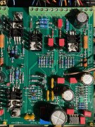
Q1L looks somewhat beat up in the photo, can't really tell if it is just the photo or real. There is what appears to be a solder splash on top of the plastic case on Q9L that if it is, may be something that comes loose later on and causes problems.
I thought you ordered the Phoenix kit but I notice you have your bias transistor wires coming in on the topside rather than the bottom side of the board and you did not use the 3 pin Phoenix for this purpose. ??? Did you extend the bias transistor leads? I don't think the originals are long enough to reach the board front side. The bias transistor leads should be kept as short as practical which is why they enter from the back side.
Screws for the transistors Q2, Q2, Q6L and Q9L are flipped over. Screw head should enter from the bottom side of the board and the internal tooth lockwasher and nut should be on topside. Heat sink compound does no harm but is not needed.
That is what I observe so far Peter. Really need to see a bottom side photo too.
- Joined
- Jan 11, 2021
- Messages
- 22
")
- Joined
- Jan 11, 2021
- Messages
- 22
@Gepetto- I did get the phoenix kit, but not the 3 pin sockets, the bias wires do reach
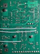
here is the bottom photo
thanks for your insight
Best
Peter
here is the bottom photo
thanks for your insight
Best
Peter
Attachments
-
 1.1 MB Views: 24
- Joined
- Nov 1, 2014
- Messages
- 3,243
- Location
- Gaston, SC
- Tagline
- Victim of the record bug since age five
@Gepetto- I did get the phoenix kit, but not the 3 pin sockets, the bias wires do reach
here is the bottom photo
thanks for your insight
Best
Peter
here is the bottom photo
thanks for your insight
Best
Peter
- Joined
- Nov 1, 2014
- Messages
- 3,243
- Location
- Gaston, SC
- Tagline
- Victim of the record bug since age five
Peter you should clean your board again, You have a lot of residue and some solder balls left behind. The cleaning should leave the board surface whistle clean.
Also touch up some of your joints if you want it to be reliable. The photo shows cold solder in some areas of the photo. Work to get your board to look like this.
Also touch up some of your joints if you want it to be reliable. The photo shows cold solder in some areas of the photo. Work to get your board to look like this.
Last edited:
- Joined
- Jan 11, 2021
- Messages
- 22
so one step forward, two backward.
The original 410 pre drivers all measured OK, however, when installed, the 10ohm resistors want to provide magic smoke and the current draw hits 1.5Amp plus - so is the MJ15022G a decent replacement for the 401's?
There is also the speaker protection board installed- and relay not engaging (as expected)
Thanks again