That's correct. I'll start putting together the care package tonight. What do you have for a soldering Iron? Desolderer or solder sucker? The traces on that board are not forgiving of overheating. You need to melt the solder and get the component OUT!
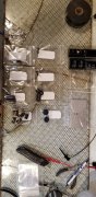
Cut the leads on the transistors if you can and remove one at a time. Trying to melt all 3 leads and get it pulled exposes those traces to wayyyyy to much heat. On the caps, melt one pad while pushing the cap sideways to get that lead pulled, then do the other. A little cool down between leads is not a bad idea either.
Search and dowload the datasheets for TIS97's, MPSA93's, 2N3439, and 2N5416. Download the datasheets for whatever is in there for transistors now so you can compare pinouts and install the new parts in the correct orientation.