
PL 700 II Clair Bros Rising from the Ashes
- Thread starter Peter S
- Start date
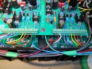
Seventeen steps back.......a small spike in current (maybe 200 mA) then all seemed normal.....until I tried to adjust the bias on the Left channel. Should have checked my work a little closer, I put the new bias transistor in the solder pads meant for the old transistor! The 5088 transistor is now open. Any pointers on what else I may have fuddled up?
I will start checking all semi-conductors, the mini-fuses on the back-planes are all still intact.
I will start checking all semi-conductors, the mini-fuses on the back-planes are all still intact.
Attachments
-
 4.3 MB Views: 17
Seventeen steps back.......a small spike in current (maybe 200 mA) then all seemed normal.....until I tried to adjust the bias on the Left channel. Should have checked my work a little closer, I put the new bias transistor in the solder pads meant for the old transistor! The 5088 transistor is now open. Any pointers on what else I may have fuddled up?
I will start checking all semi-conductors, the mini-fuses on the back-planes are all still intact.
I will start checking all semi-conductors, the mini-fuses on the back-planes are all still intact.
Did you have just the bottom row of drivers installed when this occurred?
Temporarily put a jumper between C-E of the bias transistor and attempt bring up again on the DBT. You won't be able to adjust the bias with the jumper in place but you will be able to see if the amp zeroes out on offset voltage. I would measure the 2 10 ohm bias resistors on the backplane to ensure that you did not roach them.
Seventeen steps back.......a small spike in current (maybe 200 mA) then all seemed normal.....until I tried to adjust the bias on the Left channel. Should have checked my work a little closer, I put the new bias transistor in the solder pads meant for the old transistor! The 5088 transistor is now open. Any pointers on what else I may have fuddled up?
I will start checking all semi-conductors, the mini-fuses on the back-planes are all still intact.
I will start checking all semi-conductors, the mini-fuses on the back-planes are all still intact.
I have a X-Mas party to attend so I only have a few moments.....otherwise I would check out a few more things before posting this.
Anyway.....
Peter,
Just to be sure... you removed the original 2N3403 transistors from the "P" strap and installed a 2N5088?
Joe,
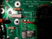
I haven't completed the assembly of an amp yet with the back-planes I have. So I need to have you clarify a few things for me since the instructions didn't seem to provide a lot of detail on wiring and mounting the bias transistor. So I am assuming that when a 2N5088 is wired to the back-plane board that one should use the holes identified for the 2N5088 and not 2N3403? I haven't looked at the datasheets lately but my guess is that two of the base, emitter or collectors is wired differently.
Perhaps also when someone replaces the 2N3403 with a 2N5088 they should use some acetone (or other material) and remove the 2N3403 lettering. Otherwise some confusion may result.
It looks like the bias transistor also is no longer mounted to the chassis but to the back-plane board? Is this correct?
If so, how does the bias transistor do an effective job of thermal tracking the amplifier? Do you use a stand-off spacer mounted to the heat-sink?..........
Ed
I did not use a DBT, I will accept one "I told you so" for that. I was watching the AC mA meter and there was next to no current draw until that one little 'blip', maybe at the 20 or 30 VAC point. The bottom row (drivers) were installed----just now removed them to test (both OK).
I will test the 10 ohm resistors, then, if they are good, bypass C-E as you describe. BTW, the offset on that (left) channel was zero even with the blown 5088 transistor.
I will test the 10 ohm resistors, then, if they are good, bypass C-E as you describe. BTW, the offset on that (left) channel was zero even with the blown 5088 transistor.
Hi Ed;
I think I can answer that, in spite of 'blowing' any credibility I might have had here, The bias transistor is mounted on an aluminum standoff, and Yes, there are two sets of holes, CLEARLY marked for old or new transistor types......I must have been day dreaming to have made this glaring mistake!
I think I can answer that, in spite of 'blowing' any credibility I might have had here, The bias transistor is mounted on an aluminum standoff, and Yes, there are two sets of holes, CLEARLY marked for old or new transistor types......I must have been day dreaming to have made this glaring mistake!
Very strange....I removed the incorrectly installed bias transistor (2N5088) and found it to be good. I am comparing it to the new pair that I have for the second amp (next project) I was confused (yet again) because my Fluke meter, in junction test mode, did not beep until I warmed the transistor with my fingers. The workshop is cold.
10 ohm resistors good on back plane. D1L, D2L, D3L, and D4L checked OK on the PL14_20 board. I thought I would check them because look like they are closely related to the bias resistor.
I correctly installed the same bias transistor that was in the wrong holes. Very slowly powered up the amp, watching the mA meter on my Variac.
Again, no current draw at all, until about 25 VAC, and then a sudden current pulse. The amp sat over night. This current pulse was not repeated after the amp was off for 30 minutes. Could it be related to the main filter caps being fully discharged?
BTW, now the bias voltage is adjustable via the pot.
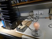
So today the amp seems to start drawing current smoothly as the variac is slowly increased. I decided to follow direction and build a DBT with a bulb bypass switch. Searching this forum, it seems a 100 W bulb is about right. With the variac at 125 VAC, there is a dim glow that does not extinguish. There is only the bottom driver row of outputs installed, zero DC offset, bias on both channels is 0.350 V Is this dim glow normal? (about 350 mA AC line current). 15 Volt supply test points on PL14_20 rev G1 board measure OK. Are there any other tests that should be performed before moving on to the second row of output devices?
Thanks again all, for all your input on this project,
Thanks again all, for all your input on this project,
Attachments
-
 4.2 MB Views: 7
So today the amp seems to start drawing current smoothly as the variac is slowly increased. I decided to follow direction and build a DBT with a bulb bypass switch. Searching this forum, it seems a 100 W bulb is about right. With the variac at 125 VAC, there is a dim glow that does not extinguish. There is only the bottom driver row of outputs installed, zero DC offset, bias on both channels is 0.350 V Is this dim glow normal? (about 350 mA AC line current). 15 Volt supply test points on PL14_20 rev G1 board measure OK. Are there any other tests that should be performed before moving on to the second row of output devices?
Thanks again all, for all your input on this project,
Thanks again all, for all your input on this project,
With the bias set to 0.35V, the output drivers are dissipating ~7W per channel or 14W for the both channels. This is the class A steady state current through the drivers you are seeing. Thus you see the DIM bulb which is what you expect. Thus the name Dim Bulb Tester.
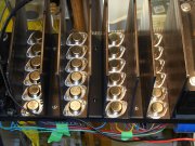
Got totally loaded just in time for Christmas! Row by row, off-set stayed at zero mV. After 10 minutes of idling, bias was set to .360 V. I will connect inputs and Led meters. Unless I'm overlooking something, is the amp ready for the dummy load for the power output test?
Merry Christmas All, and thanks for all the help!
Merry Christmas All, and thanks for all the help!
Attachments
-
 4.5 MB Views: 25
Got totally loaded just in time for Christmas! Row by row, off-set stayed at zero mV. After 10 minutes of idling, bias was set to .360 V. I will connect inputs and Led meters. Unless I'm overlooking something, is the amp ready for the dummy load for the power output test?
Merry Christmas All, and thanks for all the help!
Merry Christmas All, and thanks for all the help!
All may not be well;
With inputs wired as per WO schematic, sig gen and sacrificial speaker connected, there is a load hum. A slight tingle is felt when touching the chassis or heat fins. Measured approx 60 VAC to my building ground to chassis. Voltage decreases when I touch the chassis. The (leakage) is more or less the same, 10 volts less when I reverse the line cord polarity. Voltage (and hum) are gone when a jumper is connected from the chassis to a wall outlet ground.
The transformer bolts are still insulated from transformer lams and chassis. The transformer itself is not isolated from the chassis. That would possibly require shims between the cast end bell-capacitor saddle and the lamination stack-----if this is even a solution. I gather that it is a good practice to isolate the bolts (prevent eddy currents), but has anyone had to isolate the whole transformer from the chassis?
Fluke meter reads "infinity" from the primary windings to the chassis.
I will search this forum, but has anyone had experience with transformer trouble?
Thanks again, Peter
S
Hi Peter
Proceed carefully, you may have a safety issue here, possibly with that transformer (rare). Your DMM does not produce enough voltage to determine if you have an insulation breakdown, you need a hipot tester for that. Are you seeing that same 60VAC chassis voltage when you remove all 4 rail fuses? Should be one of your first checks. If you still are experiencing that you need to nail down that problem before going much further.
All may not be well;
With inputs wired as per WO schematic, sig gen and sacrificial speaker connected, there is a load hum. A slight tingle is felt when touching the chassis or heat fins. Measured approx 60 VAC to my building ground to chassis. Voltage decreases when I touch the chassis. The (leakage) is more or less the same, 10 volts less when I reverse the line cord polarity. Voltage (and hum) are gone when a jumper is connected from the chassis to a wall outlet ground.
The transformer bolts are still insulated from transformer lams and chassis. The transformer itself is not isolated from the chassis. That would possibly require shims between the cast end bell-capacitor saddle and the lamination stack-----if this is even a solution. I gather that it is a good practice to isolate the bolts (prevent eddy currents), but has anyone had to isolate the whole transformer from the chassis?
Fluke meter reads "infinity" from the primary windings to the chassis.
I will search this forum, but has anyone had experience with transformer trouble?
Thanks again, Peter
With inputs wired as per WO schematic, sig gen and sacrificial speaker connected, there is a load hum. A slight tingle is felt when touching the chassis or heat fins. Measured approx 60 VAC to my building ground to chassis. Voltage decreases when I touch the chassis. The (leakage) is more or less the same, 10 volts less when I reverse the line cord polarity. Voltage (and hum) are gone when a jumper is connected from the chassis to a wall outlet ground.
The transformer bolts are still insulated from transformer lams and chassis. The transformer itself is not isolated from the chassis. That would possibly require shims between the cast end bell-capacitor saddle and the lamination stack-----if this is even a solution. I gather that it is a good practice to isolate the bolts (prevent eddy currents), but has anyone had to isolate the whole transformer from the chassis?
Fluke meter reads "infinity" from the primary windings to the chassis.
I will search this forum, but has anyone had experience with transformer trouble?
Thanks again, Peter
Proceed carefully, you may have a safety issue here, possibly with that transformer (rare). Your DMM does not produce enough voltage to determine if you have an insulation breakdown, you need a hipot tester for that. Are you seeing that same 60VAC chassis voltage when you remove all 4 rail fuses? Should be one of your first checks. If you still are experiencing that you need to nail down that problem before going much further.
Hi Fred;
Wouldn't a shorted sil-pad put DC on the chassis (and blow a fuse), rather than AC?
Hi Joe;
I can remove the rail fuses but would the un-fused B+ and B- connections to the control board still cloud the issue? How about disconnecting the control board also?
I don't have access to a 'megger' or Hi-pot tester. I realize the limitations of the Fluke meter but can I at least can I assume that there is not a hard short (given that the voltage decreases when I touch the chassis)?
This could be why this amp died in the first place.... I will have to re-read all documentation, but at one point, was there a test for isolation between the transformer laminations and the chassis?
I think you have the Phoenix connectors, if so, take the control board out all together and tape off the backplane connection wires. Do your debugging of this problem with the minimum of other items installed.
Last edited: