
Full Or Quasi Comp
- Thread starter TapeHeadOne
- Start date
Hi guys,
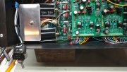
Well I decided to update the line cord to a three prong type. The ground wire went under one of the nuts securing the xformer and the hot and neutral wire extended to a double pole single throw switch which I mounted to panel. I know I hesitated but put switch on panel.
The l.e.d lites shows when power is on.
I'm still waiting for light kit to complete the amp. Got backplane assembly done and can't wait to hook up control board.
Been busy with honey do and getting house ready for winter.
I'll keep everyone posted.
Wayne in Dwight
Hi guys,
Well I decided to update the line cord to a three prong type. The ground wire went under one of the nuts securing the xformer and the hot and neutral wire extended to a double pole single throw switch which I mounted to panel. I know I hesitated but put switch on panel.
The l.e.d lites shows when power is on.
I'm still waiting for light kit to complete the amp. Got backplane assembly done and can't wait to hook up control board.
Been busy with honey do and getting house ready for winter.
I'll keep everyone posted.
Wayne in Dwight
You may end up with hum problems Wayne by connecting the safety ground to chassis. It is system dependent.
You may end up with hum problems Wayne by connecting the safety ground to chassis. It is system dependent.
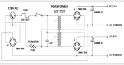
The reason I ask is that an old guitar amp technician's trick is to attach the power wire ground (green wire) to the same point as the transformer center tap 0V point to reduce ground loops and hum. The theory is that the out-of-phase secondaries cancel each other and these two connections to the chassis at the same point prevent a ground loop because there is no longer a path through the chassis. Does this make sense to you?
Interestingly, Nelson Pass used a rectifier bridge on his amps for a ground isolation. The attached view shows dual output secondaries, but could be just the same with a single center-tapped output secondary.
Attachments
-
 39.2 KB Views: 33
Joe, I was looking at the old PL 400 and 700B schematics and it shows the secondary windings of the power transformers are center-tapped to balance the rail voltages. Is this 0V connection "grounded" inside the transformer housing? Because I don't see this connection inside the amp.
The reason I ask is that an old guitar amp technician's trick is to attach the power wire ground (green wire) to the same point as the transformer center tap 0V point to reduce ground loops and hum. The theory is that the out-of-phase secondaries cancel each other and these two connections to the chassis at the same point prevent a ground loop because there is no longer a path through the chassis. Does this make sense to you?
Interestingly, Nelson Pass used a rectifier bridge on his amps for a ground isolation. The attached view shows dual output secondaries, but could be just the same with a single center-tapped output secondary.
Those center taps are typically the 2 magnet wire with woven sleeving brought out and soldered to the middle of the copper bus bars. It is a typical full wave center tapped transformer configuration.
hi Guys and Girls,
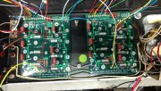
Just got my WO boards and backplane assembled and wired up and works first time. I had a problem with bias but it was because I wasn't at right t.p.
Dropped a few notes to Joe and with a quick reply I was on my way.
Big problem I had, Was putting in those Trannies. After a while I've got the hang of it.
Lastly I'm wiring up the new LED VU board.
The front panel on this PL one is not perfect so I installed a power switch to left on first VU meter.
I also have a output protector board I will install to.
I think these amplifiers should have a slow start circuit on AC input also. Being two large capacitors across the rectifier bridge it would help last longer.
I'll keep you all posted.
- Joined
- Jan 14, 2011
- Messages
- 74,243
- Location
- Gillette, Wyo.
- Tagline
- Halfbiass...Electron Herder and Backass Woof
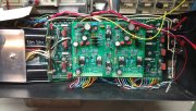
These pictures are not completed yet. I have another DCP board made by Tech America. Installed it today but needed a dropping voltage for it. Made a Zener dropping supply for 24 volts from the +75 volts side of cap
Finished installing the L.E.D meter kit today and might wrap it up this week.
Hear no hum on speaker output yet but haven't drivin it with any input source yet.
we'll keep the forum informed.
have a good night all
Finished installing the L.E.D meter kit today and might wrap it up this week.
Hear no hum on speaker output yet but haven't drivin it with any input source yet.
we'll keep the forum informed.
have a good night all
- Joined
- Jan 14, 2011
- Messages
- 74,243
- Location
- Gillette, Wyo.
- Tagline
- Halfbiass...Electron Herder and Backass Woof
- Joined
- Jan 14, 2011
- Messages
- 74,243
- Location
- Gillette, Wyo.
- Tagline
- Halfbiass...Electron Herder and Backass Woof