
What To Use Under The Power Transistors?
- Thread starter mlucitt
- Start date
- Joined
- Jan 14, 2011
- Messages
- 74,217
- Location
- Gillette, Wyo.
- Tagline
- Halfbiass...Electron Herder and Backass Woof
- Joined
- Jan 14, 2011
- Messages
- 74,217
- Location
- Gillette, Wyo.
- Tagline
- Halfbiass...Electron Herder and Backass Woof
- Joined
- Jan 14, 2011
- Messages
- 74,217
- Location
- Gillette, Wyo.
- Tagline
- Halfbiass...Electron Herder and Backass Woof
Picked some of these up last month.
https://www.digikey.com/product-detail/en/bergquist/SP400-0.009-00-05/BER212-ND/529929
Don't know if they are the best to use but work for me.
https://www.digikey.com/product-detail/en/bergquist/SP400-0.009-00-05/BER212-ND/529929
Don't know if they are the best to use but work for me.
In the Archives there should be a part number in the "parts" thread...
- Joined
- Jan 14, 2011
- Messages
- 74,217
- Location
- Gillette, Wyo.
- Tagline
- Halfbiass...Electron Herder and Backass Woof
- Joined
- Nov 1, 2014
- Messages
- 3,240
- Location
- Gaston, SC
- Tagline
- Victim of the record bug since age five
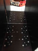
I think I am a convert to Sil-pads. Cleaning the white stuff off the mica insulators and out of these heat sink holes and from the outside and inside of the amplifier chassis probably took me about six hours (somebody used WAY too much). That includes removal of the four drivers that were still installed, removal of the heatsinks, and deburring the holes (there were several burrs from who knows what?).
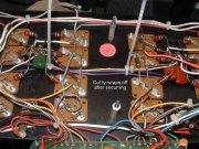
What is the consensus of the group on these capacitors on the PL400 transistor wall? They are not shown in the schematics I have. My early PL400 (serial #2225) does not have them, so I don't know the values. Are they like the ferrite beads in the PL400 Series II, an undocumented factory modification? Do they help with EMI or blocking AC? Thanks to Don for use of this picture.
- Joined
- Jan 14, 2011
- Messages
- 74,217
- Location
- Gillette, Wyo.
- Tagline
- Halfbiass...Electron Herder and Backass Woof
They are there to counteract the inductance of the wiring length in the runs that come from the bulk caps to the sockets. Also the bulk caps are not good with high frequency filtering whereas these caps are. I don’t see them on schematics and we’re not on every amp. If for the PL700, go to 250vdc. 100 will do for the PL400
What is the consensus of the group on these capacitors on the PL400 transistor wall? They are not shown in the schematics I have. My early PL400 (serial #2225) does not have them, so I don't know the values. Are they like the ferrite beads in the PL400 Series II, an undocumented factory modification? Do they help with EMI or blocking AC? Thanks to Don for use of this picture.
View attachment 35612
View attachment 35612
There were some service bulletins issued which describe the use of "slow-down" caps on the pre-drivers on the pc board also to help prevent oscillations. The 400 and 700/700B series 1 pc boards can tolerate no more than 33pF before slewing (at 20kHz) will occur. In which case the amp will not meet the THD spec at 20kHz. The series 2 PL-36 pc boards can tolerate up to 250pF. However, it is best to use the lowest value part in order to eliminate these oscillations. Arbitrarily installing values higher than needed can actually cause oscillations. As Dean use to tell me, "use the smallest band-aid possible".
Testing amplifiers at 20kHz at rated output both channels driven should always be performed to ensure that the amplifier meets factory specs! The duration of test should not be too long. Otherwise, you may run the risk of blowing the Zobel network (particularly when driving a 4 ohm load).
Ed
Last edited: